A reed relay, having a simple metallic path, will give a long and reliable life if correctly used. Despite competition from other technologies, ease of use and improvements in size and performance means that they will certainly be around for many years to come.
Graham Dale, Technical Director, Pickering Electronics
The reed relay was invented in 1936 by Bell Telephone Laboratories. Since that time, it has gradually evolved from very large, relatively crude parts to the small, ultra-reliable parts that we have today. Obviously production methods and quality systems have improved a great deal over that time and costs have come down. Pickering Electronics was founded in 1968 and even then, some were saying that these electromechanical devices would have a limited lifetime. Instead, the market for high quality reed relays has increased into areas that were inconceivable in those days.
The reed relay explained
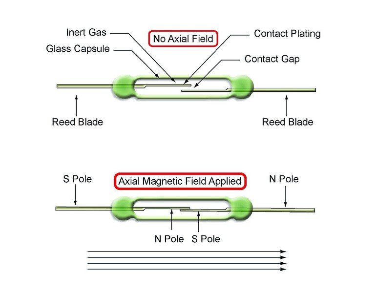
The reed switch has two metal blades made of a ferromagnetic material (roughly 50:50 nickel iron) and a glass envelope that serves to both hold the metal blades in place and to provide a hermetic seal that prevents any contaminants entering the critical contact areas inside the glass envelope.
If a magnetic field is applied along the axis of the reed blades the field is intensified in the reed blades because of their ferromagnetic nature, the open contacts of the reed blades are attracted to each other and the blades deflect to close the gap and electrical contact is made.
The reed contacts are enclosed in a hermetically sealed envelope with an inert gas, or in the case of high voltage switches a vacuum, so the switch area is sealed against external contamination. This gives the reed switch an exceptionally long mechanical life.
Various plating materials and methods are used at the switch contact areas. Most commonly, Rhodium, Iridium or Ruthenium, all rare Platinum group metals. These all provide hard, wear resistant surfaces with good resistance stability for long life, often into billions of operations. For very high voltages, 5 kV to 15 kV, tungsten tends to be the preferred material due to its very high melting point and resistance to welding due to arcing across the contacts. Reed switch contacts can be coated by either Electroplating or Vacuum deposition (Sputtering). Pickering relays intended for low level instrumentation, use Sputtered Ruthenium contacts.
Generating the magnetic field
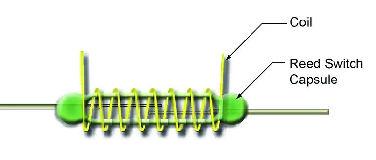
To create a relay, a magnetic field needs to be created that is capable of closing the reed switch contacts. Reed switches can be used with permanent magnets (for example to detect doors closing) but for the reed relays, the field is generated by a coil which can have a current passed through in response to a control signal. The coil surrounds the reed switch and generates the axial magnetic field needed to close the reed contacts.
Different reed switches require different levels of magnetic field to close the contact, and this is usually quoted in terms of Ampere Turns (AT) – simply the product of the current flowing in the coil multiplied by the number of turns. Again this creates a great deal of variation in the reed relay characteristics. Stiffer reed switches for higher power levels or high voltage switches with larger contact gaps, usually require higher AT numbers to operate, so the coils require more power.
Use of different wire gauges for the coil and number of turns creates relays with different drive voltage requirements and different coil powers. The resistance of the wire coil controls the amount of steady state current flowing through the coil and therefore the power the coil consumes when the contacts are closed. Whenever fine wires are used in Pickering relays, the termination leads from the coils are skeined, with several strands of wire twisted together to increase their physical strength.
Comparisons with other switching technologies
Solid state relays
Solid state relay refers to a class of switches based on semiconductor devices. There is a large variety of these switches available. Most commonly found devices that compete with reed relays are based on FET switches. A solid state FET switch uses two MOSFET in series and an isolated gate driver to turn the relay on or off. There are some key differences compared to a reed relay:
- All solid state relays have a leakage current associated with their semiconductor heritage, consequently they do not have as high an insulation resistance. The leakage current is also nonlinear and can vary a great deal with temperature. The on resistance can also be non-linear, varying with load current.
- There is a compromise between capacitance and path resistance, solid state relays with a low path resistance have a large capacitive load (sometimes measured in nF for high capacity switches) which restricts bandwidth and introduces capacitive loading. As the capacitive load is decreased the FET size has to decrease and the path resistance increases. The capacitance of a solid state FET switch is considerably higher than a reed relay.
- Reed relays are naturally isolated by the coil from the signal path, solid state switches are not, so an isolated drive has to be incorporated into the relay increasing size and cost.
- Solid state relays can have much higher power ratings.
In general reed relays behave much more like perfect switches than solid state relays since they use mechanical contacts.
MEMS (Micro-Electro-Mechanical Systems)
MEMs switches are still largely in the development stage for general usage as a relay, as they have been for over 20 years. MEMs switches are fabricated on silicon substrates where a three-dimensional structure is micro machined (using semiconductor processing techniques) to create a relay switch contact. The contact can then be deflected either using a magnetic field or an electrostatic field.
Much has been written about the promise of MEMS switches, particularly for RF switching, but availability in commercially viable volumes at the time of writing is very limited. The technology challenges have resulted in a number of vendors involved in MEMS failing and either ceasing to trade or closing down their programs.
Like reed relays, MEMS can be fabricated so the switch part is hermetically sealed (either in a ceramic package or at a silicon level), which generally leads to consistent switching characteristics at low signal levels. However, MEMS switches have small contact areas and low operating forces, which frequently lead to partial weld problems and very limited hot-switch capacity.
The biggest advantage for MEMS relays – if they can be made reliable – is their low operating power and fast response.
Like reed relays, MEMs can be fabricated so that they are hermetically sealed which generally leads to consistent switching characteristics at low signal levels. However, MEMs switches have small contact areas and low operating forces which frequently leads to partial weld problems and very limited hot switch capacity.
At their present stage of development, it seems unlikely they will compete in the general market with reed relays as the developers concentrate on high value niche opportunities and military applications.
Electro Mechanical Relays (EMRs)
Electro Mechanical Relays are widely used in industry for switching functions and can often be the lowest cost relay solution available to users. Manufacturers have made huge investments in manufacturing technology to make the relays in high volumes.
There are some notable differences between reed relays and EMRs which users should be aware of.
- EMRs are designed to have a wiping action when the contacts close which helps to break small welds and self-clean their contacts. This does help lead to higher contact ratings but may also increase wear on the contact plating.
- EMRs can have much higher ratings than reed relays because they use larger contacts. Reed relays are usually limited to carry currents of up to 2 or 3 Amps. Because of their larger contacts EMRs can also often better sustain current surges.
- EMRs typically have a lower contact resistance than reed relays because they use larger contacts and can normally use materials of a lower resistivity than the nickel iron used in a reed switch capsule.
- Reed relays exhibit much faster operation (typically between a factor of 5 and 10) than EMRs. The speed differences arise because the moving parts are simpler and lighter.
- Reed relays have hermetically sealed contacts which lead to more consistent switching characteristics at low signal levels and higher insulation values in the open condition. EMRs are often enclosed in plastic packages which give a certain amount of protection, but the contacts over time are exposed to external pollutants, emissions from the plastic body and oxygen ingress.
- Reed relays have longer mechanical life (under light load conditions) than EMRs, typically of the order of between a factor of 10 and 100. The difference arises because of the lack of moving parts in reed relays compared to EMRs.
- Reed relays require less power to operate the contacts than EMRs.
- Reed relays and EMRs both behave as excellent switches. The use of high volume manufacturing methods often makes EMRs lower cost than reed relays but within the achievable ratings of reed relays the reed relay has much better performance and longer life. With the continuing quest for further miniaturisation, better materials and production methods, it is clear that reed relays will be around for many years.
- Former-less coils
Unique construction of reed relays
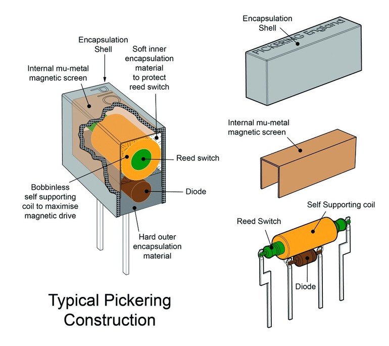
Most reed relays of the company are constructed using former-less coils which dispense with the usual supporting bobbin. This leaves more room for the coil winding, in some cases up to 50 % more, permitting smaller relays or lower current, higher resistance coils.
SoftCenter Technology
Often, reed relays are moulded using very hard materials which can cause stresses on the delicate glass/metal seal of the reed switch capsule with the risk of damage. The company instead, use a soft inner encapsulation which provides a buffer to protect the switch. Without this, stresses can distort the reed switch slightly, thereby changing the contact area, degrading performance, contact resistance stability and life.
Integral mu-metal magnetic screens
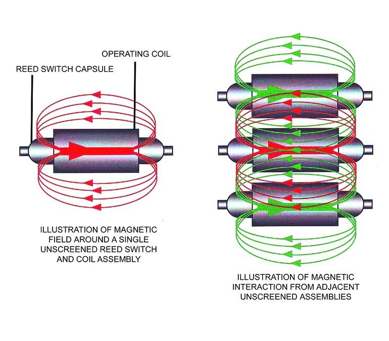
Pickering reed relays are fitted with an integral mu-metal magnetic screen. This means that the company relays can be stacked closely together without the magnetic field from one relay affecting adjacent parts.
The switch contact in a reed relay is operated by the magnetic field generated by the coil which is wound around it. When these relays are stacked close together, the field from adjacent relays will tend to oppose the magnetic field from the relay alongside, reducing its sensitivity. Look at the field illustrations in the diagram. This means that a higher coil voltage will be required to operate it. For very small relays, this increase could be as high as 40 % which means that it may not be possible to operate the relay at its normal coil voltage.
Mu-metal is used by the company for this screen, rather than steel, because of its very high magnetic permeability and very low magnetic remanence. This will allow the highest level of packing density. Magnetic screening is absolutely essential for reed relays mounted on a close pitch.
The future for reed relays
In more recent years there has been a constant quest for further miniaturisation. Smaller parts have required more sophisticated methods, including lasers, to create the glass to metal hermetic seal of the reed switch capsule. Lasers are also sometimes used to adjust the sensitivity of reed switches by slightly bending the switch blades to change the size of the contact gap. Contact plating materials and methods have also changed, particularly in the areas of cleanliness, purity of materials and the reduction of microscopic foreign particles or organic contamination resulting in superb low level performance.
Reed relay operating coils have also become smaller and more efficient thanks to advanced coil winding techniques with controlled layering of the coil winding wire. In the case of Pickering relays, the coil winding bobbin has also been dispensed with, in favour of former-less coils which has reduced package sizes. While reed relays are a relatively mature technology, such evolution will continue in the future.
Share:


