The ever-rising demands on quality can be seen in solder paste stencils and cutting elements. An application team, from the laser specialist company LPKF, examined quality features using the StencilLaser P6060 and the StencilLaser G6080 as examples. In extensive test runs, the experts scrutinized the individual aspects. They compiled the results in the LPKF tech paper titled „Quality Aspects in Solder Paste Stencils“ with the goal of optimizing universal quality criteria in various applications.
It is not always possible to obtain optimal results for cutting, engraving of text and fiducials, step-down, step-up, CW welding, punching, cutting elements, and stick-in – because even if certain processing parameters show very good results, other quality aspects may suffer.
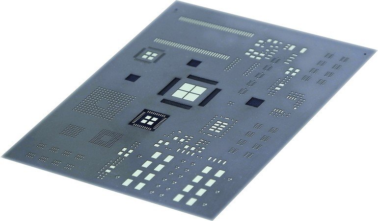
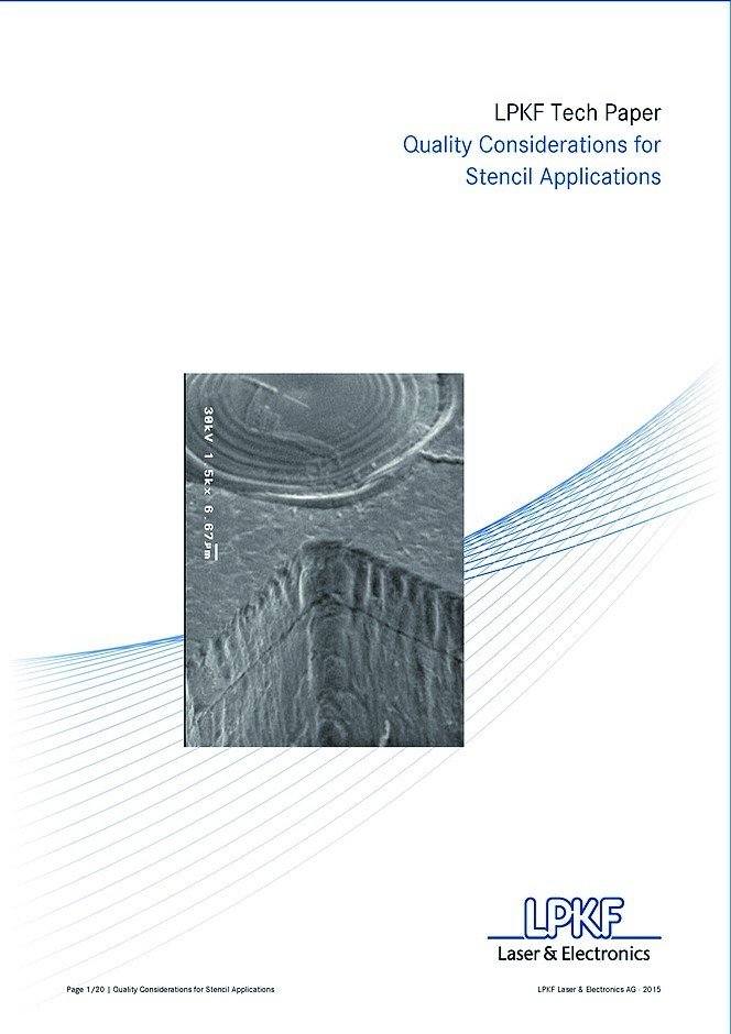
Stencil foil cutting
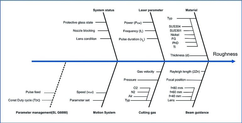
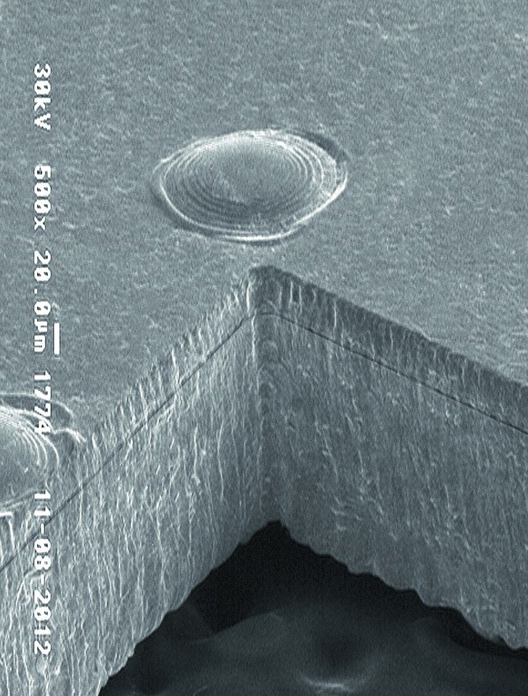
The application team chose to define quality aspects using the parameters of taper, roughness, burr, dross, and heat-affected zone for laser cutting. The unavoidable taper from the cutting process is a conical expansion of the hole in the material resulting from the difference in cutting diameter at the laser entry and exit points. For a positive taper, the laser entry side has a larger diameter than the laser exit side does. This favors release of solder paste and facilitates adhesion of the solder paste to the board when the stencil is lifted up off of the board. The position of the focal point affects the taper size. Hence, an unusually large taper can be traced back to a defocused laser beam.
A defocused laser beam increases the roughness of the cut wall, which can have a significant effect on the release of the solder paste and the efficiency of paste transfer from the stencil to the PCB. A low roughness, in contrast, leads to low friction of the solder paste on the inside wall and creates a small inside wall surface area. This also lowers the adhesion of the solder paste to the inside wall surface. The focal position of the laser additionally affects the heat-affected zone, i.e., the edge region of the cut. The amount of heat diffused through the laser beam during processing decreases with increasing cutting gas pressure but increases with material thickness. In addition, with increasing laser beam diameter, the melt volume increases, making precise in-focus work essential.
With properly adapted laser parameters, the cutting gas type, unlike the energy output by the laser beam, has almost no effect on the heat-affected zone. Hence, a lower energy input leads to a high-viscosity melt, which remains for a long time in the cutting gap and gives off heat to the edge regions. An excessively high amount of energy causes the heat that is not required for cutting to be transferred to the edge regions. The extent to which the heat penetrates into the material can only be determined precisely via elaborate material analysis. However, the discoloration in the edge region resulting from the effect of heat can be used as a measure of this.
Another quality criterion is the melt expelled on the laser exit side (dross), which should be kept to a minimum. Factors influencing dross formation are viscosity of the melt and cutting gas pressure. The extent of dross formation increases with increasing cutting gas pressure because the melt adhesion is poorer at the exit. The dross amount can also be reduced with a reduced laser power, although the roughness of the cut wall is thereby increased. For minimizing the extent of dross formation, an optimal setting of the laser energy is crucial.
For fusion cutting with microsecond pulses, burrs are unavoidable. Like dross, burrs are formed on the cutting edge on the laser exit side. The individual burr protrusions (whiskers) can be several hundreds of micrometers in height and are only weakly connected to the cutting wall edge. Burrs usually occur at the end of an aperture when the material is bent before the end of the cutting line. Parameters such as aperture shape, size, pierce position, height, and angle affect burr formation. With suitable system adjustments, the burr height can be optimized for individual apertures.
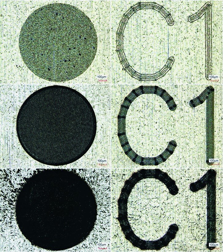
Text and fiducial engraving
Engraved texts and fiducials should be legible without causing a large amount of heat distortion. The heat distortion increases with decreasing material thickness for an average power level, whereas the contrast shows varying results. The pulse width and the power should be adapted to the materials. This also applies to fiducials, which are filled with a lower line spacing. A similar contrast can be achieved here with lower power. The contour is an important parameter for fiducials for precise read-in. Because the fiducials form the basis for step-down ablation, the melting region should not overlap the ablation region.
Optimization of step-down steps
Step-down ablation, the step surface roughness, the heat-affected zone, and the expulsion are factors that influence the processing time. For example, the roughness decreases with an increasing number of passes. When power increases the heat-affected zone size increases, hence the parameters of heat distortion and roughness increase.
Expulsion is a type of dross formed around a step. It is formed from small molten balls blown off of the step by the cutting gas. During this process, known as ablation, a higher power can lead to more material around and on the step edge.
Precision welding techniques in focus
Step-up stencils are produced through welding of sheet metal onto the step region by precision spot welding. Even if the quality criteria for spot welding differ from those applicable to step-down step production, both processes require the best possible surface quality. In the step-up process, the number of spatters and the expulsion height are important parameters. For spot welding, the joining surface and the welding depth are additional parameters to be considered. The shear strength is another important aspect because a doctor blade exerts a shear force on the weld spot during solder paste printing. As welding depth increases, the maximum force generally increases and the shear strength decreases slightly. In relation to the surface area however, the opposite applies. This is because the increase in force combined with increasing pulse width is significantly lower in comparison with the increase in joining surface. Air pockets in the weld spots decrease the shear strength.
If a continuous line, instead of a continuous weld seam, is desired in pulse mode, CW (continuous wave) welding with continuous radiation is used. The precision welding technique enables a uniform depth of weld as well as a uniform weld curvature. Here too the welding depth and the molten material volume are important. The aspect ratio, that is, the relationship between the processed weld seam depth and the lateral expansion on the surface, can be adjusted via power and speed.
In precision welding, penetration welding and conduction welding are different. In conduction welding, material is melted by heat conduction, whereas in penetration welding, higher-temperature melts generate a vapor that exerts pressure against a melt and achieves a greater welding depth through displacement. At high speeds, a vapor capillary (keyhole) forms and advances with the beam. The further the working point extends into the penetration area, the higher the aspect ratio becomes.
One pulse, one hole
Unlike precision welding, punching introduces holes into stainless steel foils by means of a pulse, whereby the hole diameter can be varied through the extent of defocussing. For small hole diameters, punching represents a time-saving alternative to cutting. „Punching on the fly“, a method in which the pulse is output at defined intervals while the material is moved, is even faster. The speed should not be set too high, though, because the path length traversed in one pulse width becomes too high and an elongated hole is produced.
Parameters such as an imprecisely adjusted nozzle, an excessively high cutting gas pressure, an average power that is too low, and a large material thickness cause surface spatters. These material deformations can lead to defocusing and disruption of the punch process. The maximum material thickness is thus restricted insofar as the heat distortion depends on the material thickness and increases with increasing melt volume. To avoid overlapping of heat-affected zones for adjacent holes, the maximum adjustable speed should be oriented to the cooling time and the size of the hole pattern.
Additionally, hole size, material thickness, cutting gas pressure, and cutting gas type affect the expulsion height. The hole size and the material thickness have an effect on the melt volume, which is proportional to expulsion and dross. Similarly to step-up welding, expulsion is lower for a cutting gas with a low oxygen content than for a cutting gas with a high oxygen content. However, expulsion, in contrast to dross, decreases with increasing oxygen content. Smaller holes can be generated with oxygen at lower material gauges. The opening ratio, or the ratio of generated holes to still-closed holes, is also higher. With decreasing oxygen content, the heat-affected zone size decreases and the maximum material thickness to be processed also decreases.
Percussion drilling in metal foils
In percussion drilling (also known as „piercing“), in order to make each aperture or cutting line, a hole is first produced in the material by pulses. Then the actual cutting process begins. Spatters are thereby produced on the material surface. They should not be too large and should be as low in number as possible because they can deposit on the inside walls of the nozzles and plug them. Deposits hamper discharge of the melt, enabling burrs to be formed on the exit side of the beam. A larger hole diameter prevents nozzle clogging but also increases the amount of molten material that must be removed from the hole.
Production of ultra-fine cutting elements with the StencilLaser
For cutting elements, cutouts in the individual parts as well as the outer contour must be considered. Cutting and fast cutting techniques allow for precise outer contours. If tabs are required for keeping parts in focus, they must be able to be separated easily from the surrounding material. The tab width varies according to material type, material thickness, and magnitude of sheet stress. For a higher material thickness, the tabs can be narrower, whereas for a higher sheet stress, the tab width must be increased. The tabs should be positioned to ensure minimal subsequent disturbance. At the same time, the contour quality can be improved through manual modification of the tab shape.
Experience helps
The company published a study of quality aspects for different applications in a tech paper, which is available in English and German for free download from the Knowledge Center on the company Web site.
SMT Hybrid Packaging, Booth 5-434
Share:


