Process challenges: Compared to other automated processes, selective soldering is considered demanding. Structures with small pitches result in a small process window, variable parameters such as flux quantity, temperatures or wetting time, play a decisive role in terms of solder joint quality and reliability. In addition, material-related influences have to be considered.
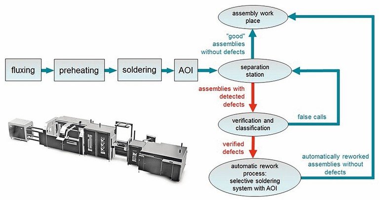
The zero-fault production concept: A controlled and reliable process is a basic requirement for approaching a zero-fault production. Besides the selective mini-wave soldering process with monitoring and control functions for all process steps, the zero-fault production concept incorporates integrated automated optical inspection (AOI) of the solder joints, as well as, a defined and automated rework soldering process at the fault coordinates, corresponding to the fault classification. This is an advantage from the technical processing point of view since only defective solder joints go through the process again, not the entire board. As all work stations are linked with a bi-directional data transfer, all process steps are completely traceable and reproducible. In addition, analysis of trend and series faults allows process optimization at an early stage. This applies particularly for component placement and the soldering process, however, design faults can quickly be identified as well.
With a focus on the critical issues in a selective soldering process, this paper will describe all process steps that need to be controlled to ensure consistently high product quality. In addition, it will describe a production concept enabling automated rework with minimal thermal exposure for the assemblies. This paper and presentation was first presented at the 2018 IPC Apex Expo Technical Conference and published in the 2018 Technical Conference Proceedings.
Introduction
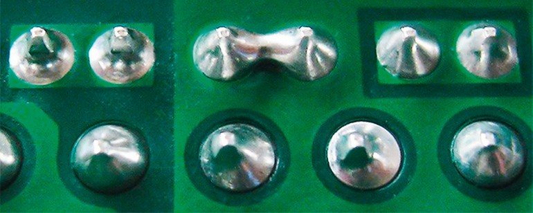
One of the most frequently experienced solder defects is the formation of solder bridges. As for many typical solder defects, the root cause might be several factors. Particularly in lead-free applications, the reduced wetting-force of the solder alloy contributes to a changing flow behavior, which may result in bridging. Solder bridges, however, also might be caused by an inadequate quantity of flux applied to the solder joints or insufficient preheating of the assembly.
Insufficient solder through-hole penetration is another typical process-related soldering defect and besides the option that the connecting partners, e.g. the printed circuit board and/or the component, show poor solderability, this defect is often related to a poor heat balance. Moreover, an insufficient flux quantity can also be the reason for this defect.
Another typical solder defect which might occur in selective soldering processes is the formation of solder icicles. Most frequently, icicles are caused by an insufficient preheat process or inadequate energy transfer during the soldering process. But also insufficient flux application can be a reason for icicle formation.
These are only some of the possible soldering defects and in many cases they are related to the flux application process or the heat transfer rate, while preheating the assembly or during the soldering process. Therefore, a controlled and reliable process is a basic requirement for approaching a zero-fault production.
Monitoring the fluxing process
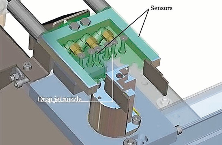
The flux makes soldering process possible, it removes the existing oxide layer and avoids re-oxidation, to allow a proper wetting process. Enough flux must be brought to the solder joints to achieve sufficient hole fill in the soldering process. On the other hand, residues on the PCB should be minimized, when using a no-clean flux type and if additional costs for a cleaning process are to be avoided. Flux residues can result in a significant loss of quality, in extreme cases causing total failure of the product. Therefore, fluxer monitoring systems are essential. There are different methods to monitor the flux deposition. The easiest way, but not the most reliable, is to monitor the function of the fluxer drop jet nozzle. Usually, this is performed in a test cycle using an appropriate sensor which is wetted, prior to the actual flux application in production. This method assures the function of the fluxer nozzle at the time of the test, however, it does not permit any conclusions to the actual production process and the flux quantity being applied to the printed circuit board cannot be clearly defined.
Real-time monitoring of the flux quantity during flux deposition in the production process is more reliable. Here, the system monitors the flux quantity that is jetted to the printed circuit board during the fluxing process. The captured value is compared with the nominal values set in the soldering program and in case of any deviation, an error message will be initiated. In addition, the cause of the error, as well as, the name of the faulty geometry can be displayed. As this method is based on a real-time system, it ensures the highest reliability and stable process conditions without any influence on the cycle time.
Control of the preheat process
Monitoring of the preheat temperatures is essential to ensure reproducible temperature profiles which again are required for activation of the flux. One of the most common and most reliable methods to monitor and control the preheat temperature is the use of infrared thermometry. Depending on the temperature, each object emits a certain amount of infrared radiation. Changing the temperature of the object goes along with a change of the intensity of the radiation. The wavelength range used for infrared thermometry, the so-called “thermal radiation”, ranges between 1 µm and 20 µm. The intensity of the emitted radiation depends on the material. This material-specific constant is described with the help of the emissivity which is a known value for most materials.
Infrared thermometers are optoelectronic sensors. They calculate the surface temperature based on the emitted infrared radiation from an object. The most important feature of the thermometers is the measurement of the objects without contact. Consequently, this helps to measure the temperature of inaccessible or moving objects without difficulties.
In connection with the appropriate software, the required preheat temperature can be preset for a printed circuit board which allows a gradient-controlled preheat temperature profile.
Controlling the soldering process
Particular attention should be given to the soldering area – the heart of the process. There are many variables which can influence the soldering results. For example, the temperature of the solder alloy and the solder level in the solder bath, which should be continuously monitored and automatically controlled. Due to the very small solder nozzle geometries that are used in selective soldering processes, it is important to ensure a constant and stable wave height which is decisive for a sufficient energy transfer to ensure a reproducible soldering quality.
Multi-wave systems typically use an eddy current sensor to control the solder wave height and it simultaneously monitors the solder level in the solder pot. A measurement funnel, which has the same level as the solder nozzles, is connected with the pump channel. Based on the principle of communicating tubes, which is an indirect measurement, the same solder wave height arises at the solder nozzles and at the measurement funnel. The signal of the eddy current sensor is continuously compared with a nominal value to keep the wave height stable.
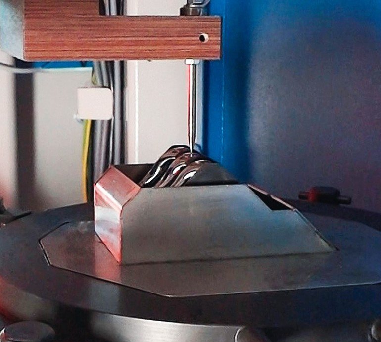
The easiest method to measure the wave height in single nozzle mini-wave processes is using a measuring needle made of titanium or any other resistant material, which performs a contact measurement at the surface of the solder wave. This causes an electrical signal and the pump speed is regulated to the necessary speed to achieve the preset wave height. As the measuring needle only carries out a contact measurement and does not dip into the solder, it is important to keep the atmosphere stable. Changes in the surface tension can lead to different measurement results.
Alternatively, the wave height can automatically be controlled using a laser measuring system. The measurement procedure is performed simultaneously with the production, and therefore, there is no influence on the cycle time. In addition, any change of the pump speed affects the measuring signal quickly. The direct measurement of the wave height also recognizes soiling in the nozzle system, which could affect the soldering results. The wide measuring range of the sensor and the adjustment to zero at the top edge of the solder nozzle enable the use of nozzles with different height.
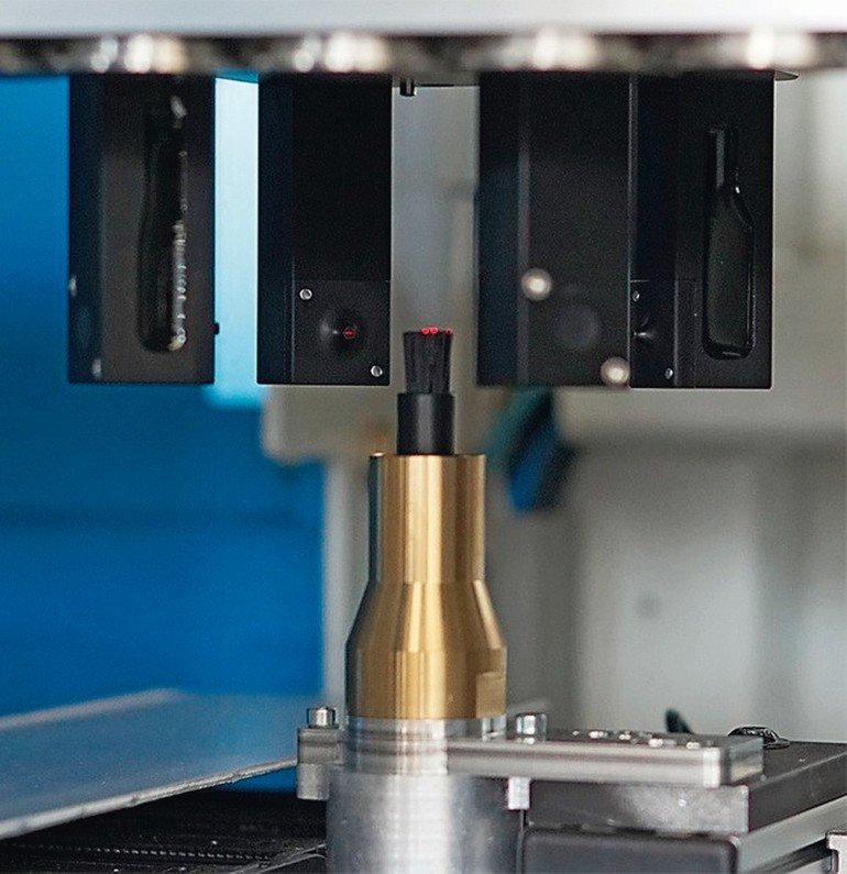
A newly developed wave height measurement system is a cross sensor that takes over several functions. On the one hand, the wave height in mini-wave soldering processes is precisely controlled. The measurement is made directly at the solder nozzle, without having to touch anything, and it is fully independent from the solder alloy used. In addition, the cross sensor is also used for automatic tool measurement: diameter, height, and mounting position of the solder nozzle are automatically controlled, thus excluding potential operator errors. The cross sensor carries out another task if additional processes are installed, such as, a brushing process for the removal of solder balls. Here, the cross sensor also monitors the condition of the brush and automatically indicates the need for a replacement if the brush is worn to a certain level.
Additional control functions help to improve process reliability and stability
Additional automatic monitoring and control functions help to avoid potential soldering defects or to eliminate operator errors. Such control functions, for example, are the automatic position correction of the x, y and z value for assemblies which show misalignment or warpage. Furthermore, an intelligent tool management based on sensors and software tools recognizes the current solder nozzle set-up and assures that only printed circuit boards are allowed to enter the selective soldering system that are designed to be processed with this set-up.
Due to the comparatively small solder volume that is available for energy transfer, selective soldering processes use relatively higher solder pot temperatures up to 320 °C. This goes along with an increased risk for oxidation. Selective soldering systems generally are operated in a nitrogen atmosphere. While the mini-wave in a nitrogen environment shows a controlled solder flow, the liquid solder rapidly oxidizes as soon as the inert atmosphere is lost. The solder flow then can be deflected easily and can hardly be controlled, which makes it difficult to produce reliable solder connections. Various control methods can be used to ensure a stable nitrogen atmosphere during the process. The quality of the supplied nitrogen can be monitored by measuring the rest-oxygen value at the nitrogen feed-in. This is particularly useful if a nitrogen generator is connected. It is also possible to permanently control the nitrogen quantity at the gas supply of the soldering unit. Here, an individual value that is needed for the specific process can be set in the soldering program (l/min).
Integrated automated optical inspection and automated rework
100 % process control is given with an AOI system that is integrated directly in the selective soldering machine, which offers significant benefits in view of the total production line. Soldering defects will be detected early, analysis of trend and series fault information allows process optimization at an early stage to reduce the overall defect rate. This particularly applies for component placement and the soldering process, however, design related defects can quickly be identified as well.
The inspection of one assembly is performed in parallel to the soldering process of the following assembly to ensure short cycle times. The integrated AOI system allows the inspection of solder joints for remaining solder balls, non-wetting or insufficient wetting, missing pins, bridging or removed neighboring SMD components. As the soldering unit and the AOI system are using the same x/y axis system, this solution also provides high efficiency.
In a subsequent separation module, assemblies without defects and assemblies with defects are automatically separated. Verification and classification of soldering defects is made at a verify work place. Afterwards, the assembly can be processed with another soldering system, or alternatively can pass through the same selective soldering machine a second time. In both cases, an automatic rework process will be performed exclusively at the solder joints that were classified with a defect. This is a large advantage from the technical processing point of view, as only defective solder joints go through the process again, not the entire board. As all work stations of this production concept are linked with a bi-directional data transfer, all process steps are completely traceable and reproducible.
Conclusion
To ensure consistently high product quality and finally reach a zero-fault production stage, it is necessary to control all process steps. Manual rework is costly and does not always provide the required quality. In addition, manual rework is difficult to trace. Automated control functions and – if necessary – automated rework offer both repeatability and traceability, which are independent from human actions.
SMT Hybrid Packaging, Booth 4–141
Zusammenfassung Résumé Резюме
Mit Fokus auf die kritischen Punkte eines selektiven Lötprozesses beschreibt der Artikel alle benötigten Prozessschritte, um eine konstant hohe Produktqualität sicherzustellen. Zusätzlich wird ein Produktionskonzept beschrieben, welches einen automatisierten Reworkprozess mit minimaler Belastung für die Baugruppen ermöglicht.
Sur les points essentiels d’un procède de soudure sélectif, l‘article décrit toutes les étapes nécessaires pour constamment garantir une haute qualité de produit. D’autre part, un concept de production est décrit, qui permet un procède de reprise automatique avec un minimum de tension sur les assemblages.
В статье рассматриваются критически важные аспекты селективной пайки и описываются необходимые шаги для обеспечения стабильно высокого качества продукции. Дополнительно описывается концепция производства, обеспечивающая автоматизированную доработку брака с минимальной нагрузкой на узлы.


